 |
|
|

Contact email: [email protected]
Twitter https://twitter.com/G4NSJ
![]()
An audio welcome 13/09/23
Hi, I’m Ray. I was first licenced in the 1960s with the call, G8CUH. That was after many years of short wave listening, firing up WS No 19 sets, 52 sets, 22 sets, 18 sets, 62 sets, a B44 on 4 metres and a host of other army surplus gear. There was so much gear available in those heady days! I then took the morse exam at HM Coastguard North Foreland, GNF. And I became G4NSJ. That was a happy day!
In my early teens, I’d tune around 160, 80 and 40 metres and listen to the old boys chatting about aerials. Those knowledgeable gents had been around for years and they’d learned from experimentation and experience, and they knew what they were talking about. I learned from them, making notes about the aerials they were discussing as well as listening intently to their musings about transmitters, receivers, ATUs and everything radio.
Now, I’m an old boy chatting about aerials, ATUs and whatever. Well, I’m not that old! What I aim to do with this web site is help newcomers to the hobby, and perhaps procure some interest from old timers. So, newcomer or old timer, I hope you find my site interesting and useful.
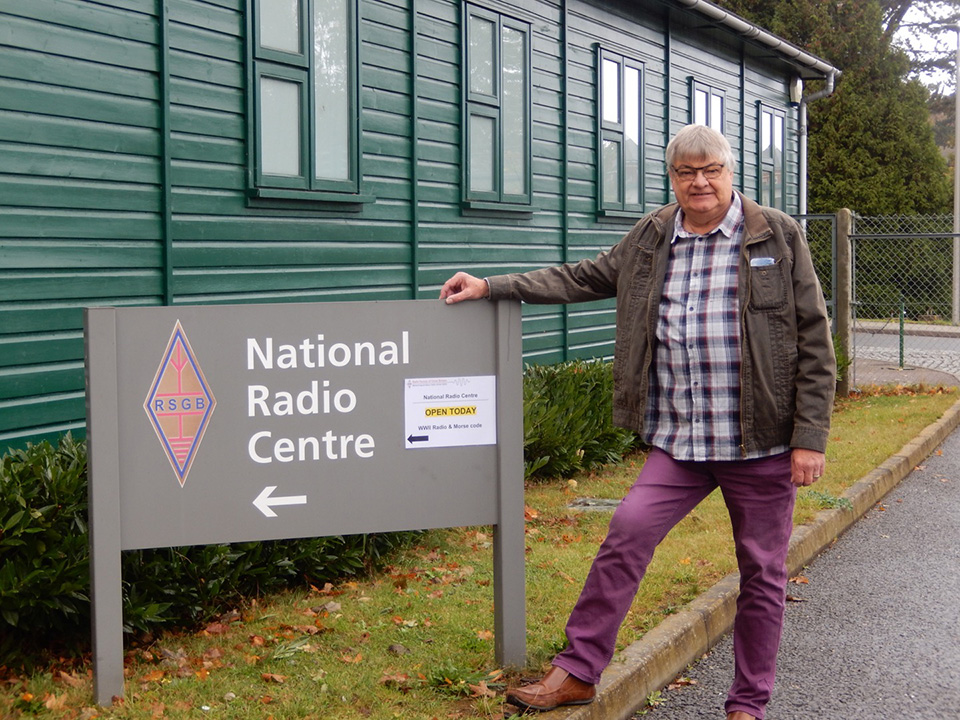
THE NATIONAL RADIO CENTRE:
Here I am at GB3RS Bletchley Park. A great day out!
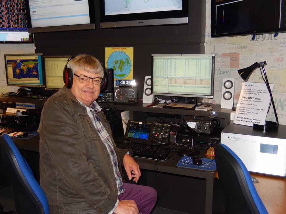
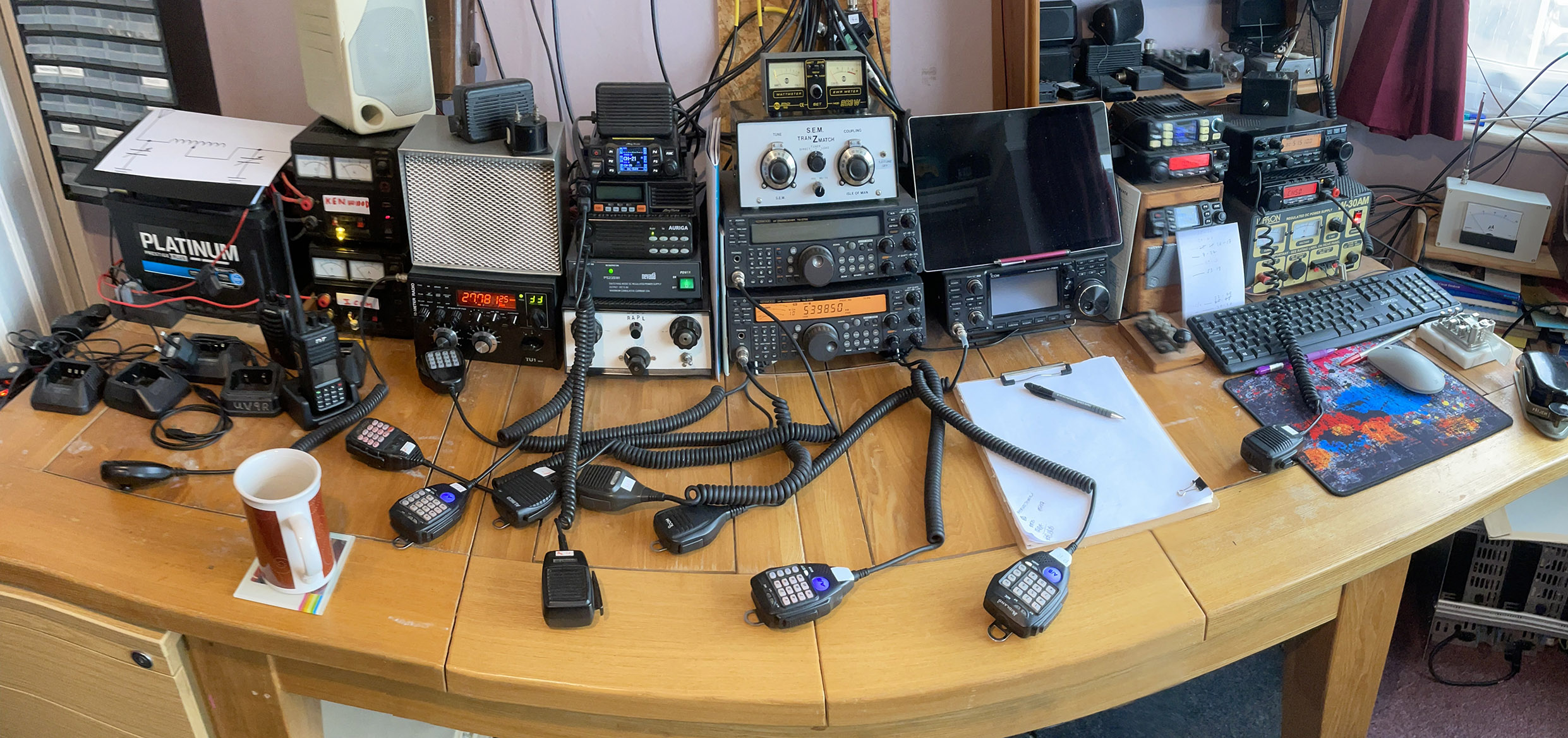
THE RADIO ROOM (shack):
My radio room, or shack, is upstairs in what was the front bedroom. I monitor 10 metres FM, 6 metres FM, 4 metres FM, 2 metres FM and our local 2 metre and 70cms repeaters. As you can see in the photo, there are 10 microphones and 2 Morse keys! I also monitor 5MHz. Update: it’s now 2023 and I have 11 microphones and 3 Morse keys on the desk. Oh, and an Icom IC-7300 and… loads of other stuff. Photo update 13/3/22
Below is another, wide angle, shot of the radio room.
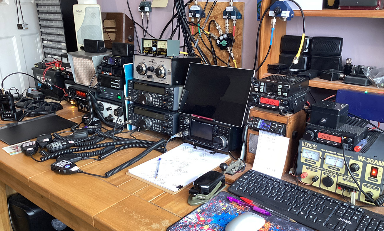
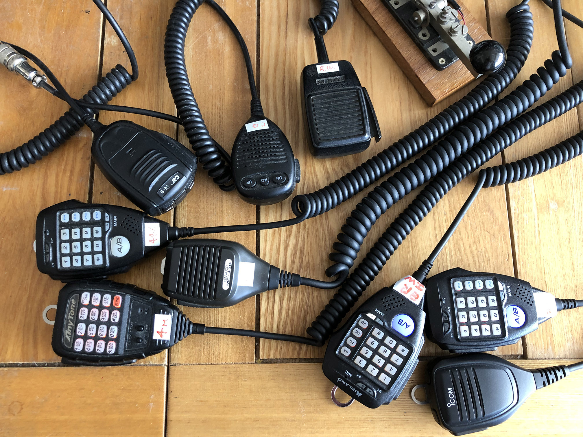
Microphones:
I don’t like the so-called shack in a box radios where you have HF – 6 metres – 4 metres – 2 metres – 70cms and more all in one radio. I like to listen on all bands at once! The drawback is… microphones. Shown below is a selection of a few of my microphones which are connected to their corresponding radios.
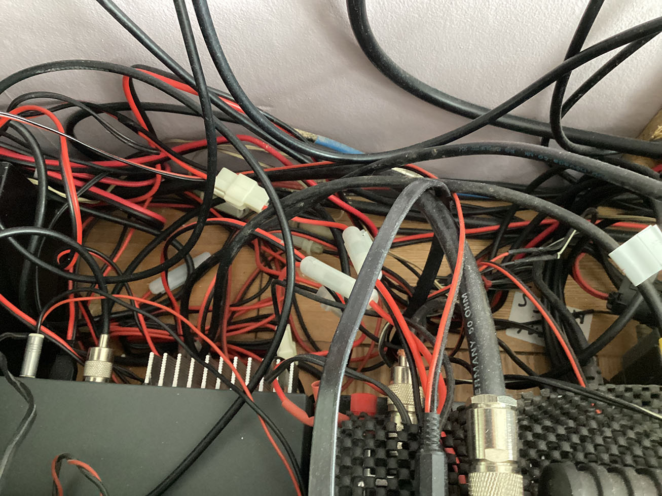
Do you have this problem:
There’s no way round this mess. Here is a small section of the scene behind the radios.
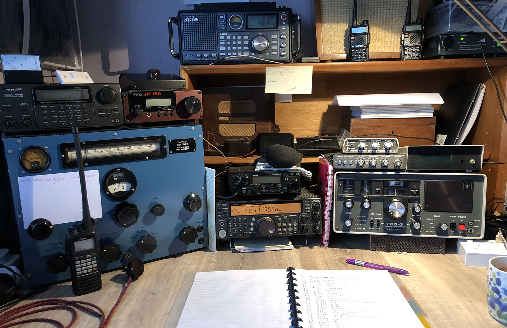
MY RECEIVING STATION:
Below is my receiving set up where I do all my short wave listening. I like to tune around outside the amateur bands and listen to military comms, shipping, aircraft and broadcast stations so this is ideal. The signals feeding this lot come from a MiniWhip active antenna which can be switched to each receiver in turn. My favourite reciever is the Marconi CR100. On top of the CR100 is my Lowe HF-150. No doubt you’ve spotted the Yaesu FRG-7 which is another oldie.
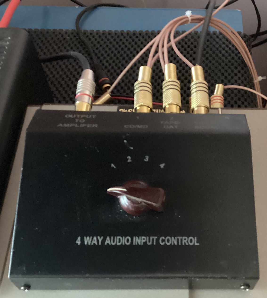
The MiniWhip active antenna can be switched to each receiver in turn, as shown below. I fitted a six-way rotary switch in the box and used the RCA photo sockets for aerial input and outputs. There’s no matching problem as it’s for receive only. As a matter of interest, Heathkit and Collins used RCA antenna plugs and sockets on their gear.
ON THE AIR:
I’m active on two metres, mainly monitoring GB3RW the 2 metre repeater in Worthing, West Sussex. I can also be found on the Isle of Wight repeater, GB3IW from time to time. I monitor 70.450MHz on the 4 metre amateur band so give me a call if you’re within range. I’m also on 10 metres, monitoring GB3CQ, a repeater located in Worthing: output on 29.630 FM with a tone of 88.5Hz to access the repeater. There is some sporadic E from time to time but I’m looking forward to the band really opening up! Oh, I almost forgot about 6 metres. I monitor 51.510MHz FM. Last but not least, I monitor channel 8 on 446 PMR.
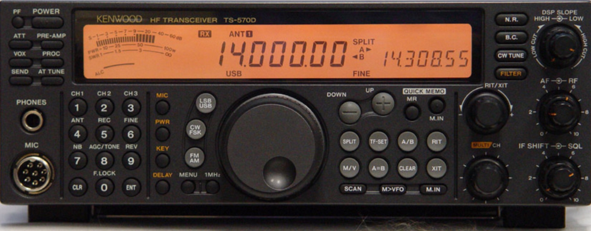
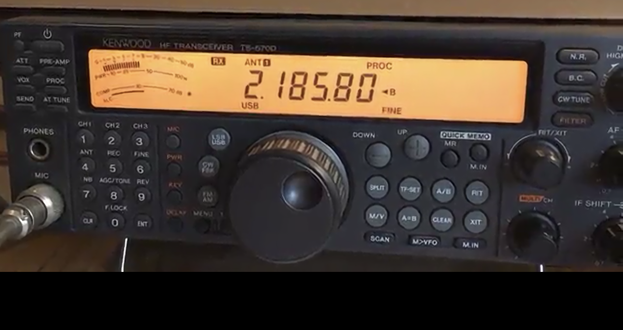
My HF radio was a Kenwood TS570D. (See update below) It’s a nice radio, when I can hear above the horrendous noise level! Unfortunately, I suffer from bad interference on the lower bands. 160 and 80 metres are usually wiped out by noise. My main HF aerial is a 132 foot doublet fed with 300 ohm ribbon. It runs from the back garden, over the house to the front garden – hence the interference from mains wiring and noise from phone lines in the street carrying ADSL. Fortunately, the 5MHz frequencies relatively free of interference.
UPDATE: January 2022
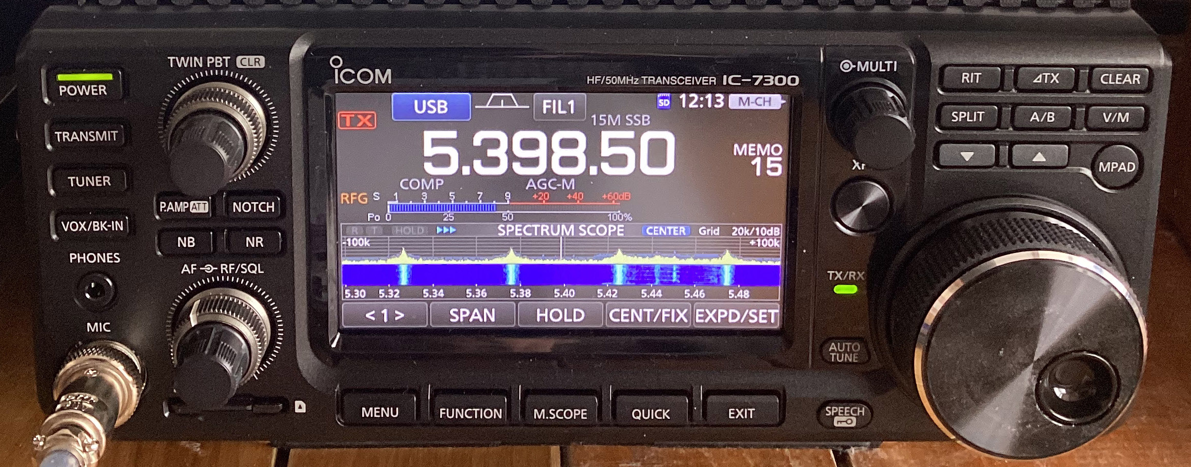
I’m now the proud owner of an Icom IC-7300. This is a fantastic piece of kit and I’ll be writing more about it once I’ve got to grips with it. One thing I have discovered is the noise blanker and reduction work extremely well. One problem is the solitary aerial socket on the rear panel. Why aren’t there three sockets? Information on my coax switching arrangement here.
ECHOLINK:
I’m not keen on EchoLink but it can be useful at times. For example, I can listen to myself through certain repeaters to check my signal strength into the repeater. If you have EchoLink, try searching for my callsign. If I’m listed, give me a shout.
 MORSE CODE:
I recently had my first CW contact in 35 years! I’ve not been on the key since the seventies so I’m brushing up on my Morse code. I’ve just acquired a new (lovely old) Morse key which I believe was the type issued to the Czech army in the early fifties. It’s easy to adjust and really nice to use. I’m now pretty good at 12 wpm so I hope to begin having regular contacts on the air before too long. 15 wpm is my goal at the moment. Oh, and I’ve just joined FISTS CW Club. 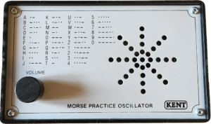
A practice oscillator is useful but, if you’re just starting out with Morse code, don’t touch a key until you’re receiving 12 words per minute. There’s more about Morse code here.
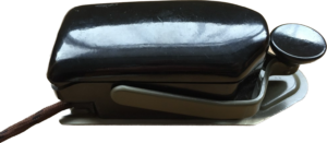
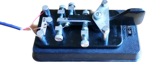
Here is my 8 amp Morse key. It’s a basic 1940s key but very nice to use. I 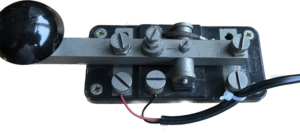 don’t know why it’s called an 8 amp. Does anyone know? These were fitted to field telephones during the war years. I had several back in the 60s but they’ve all disappeared. Thanks to Tony for donating this one.
 This is my single paddle key, the Hi-Mound Manipulator MK-701. Paddles are great if you’re sending shed loads of CW. Straight keys can make your wrist ache… that’s what I find, anyway. Perhaps you disagree?
I’ve just bought a dual paddle Iambic key! It’s a Hi-Mound MK-703, used but in great condition. I began using a twin paddle key in the early 1980s, exactly like the one shown here, and I really 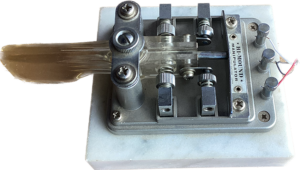 have missed it. To be honest, I didn’t use it in true Iambic mode. For the straight key brigade shaking their heads negatively, I also use my straight keys. There’s more on Morse keyes here.
2 METRES – 70CMS:
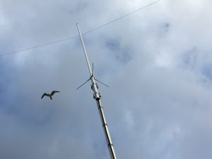
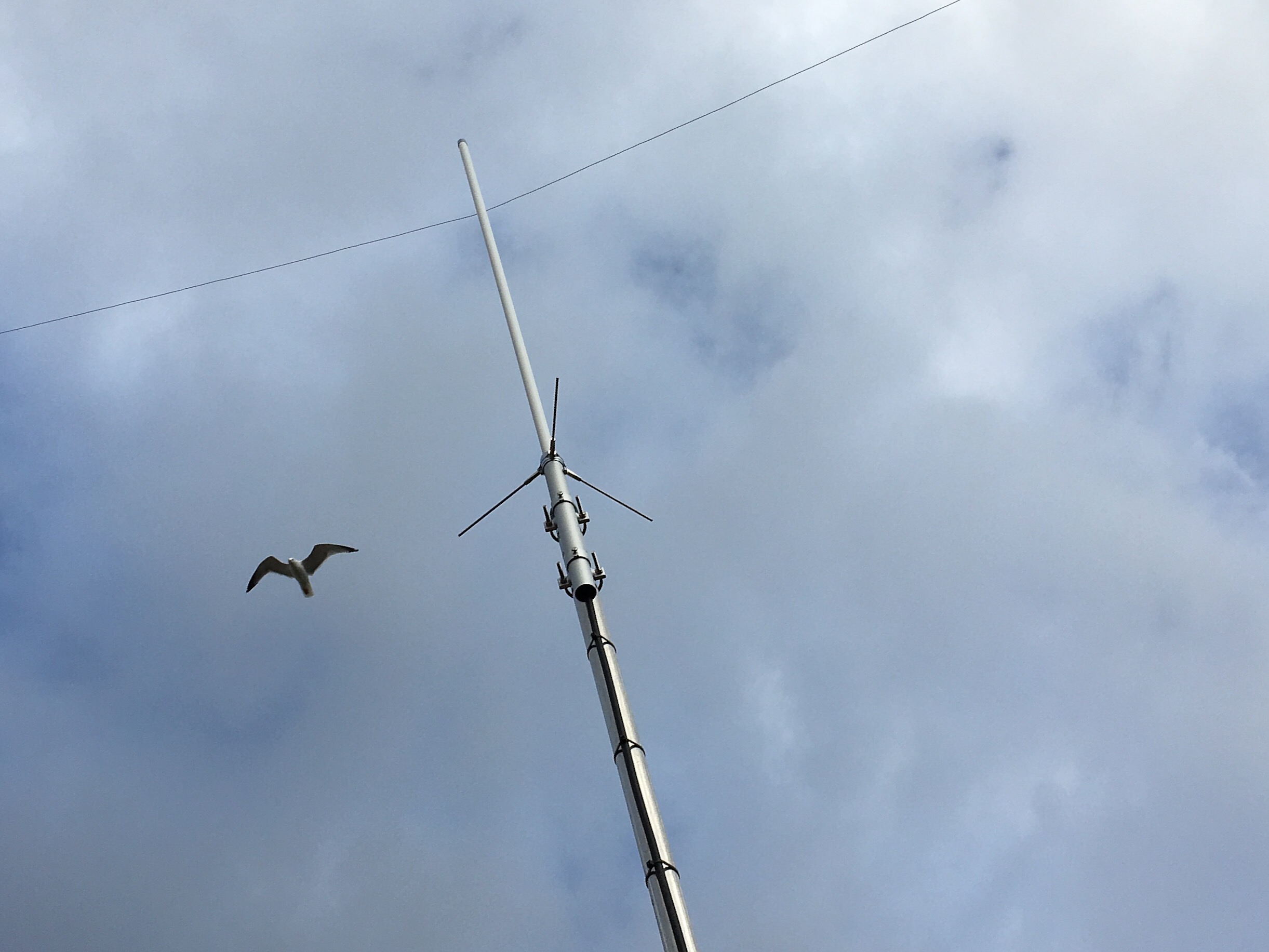
This is my 2 metre – 70cms collinear aerial. It’s the Watson W50. The aerial was on a pole in the garden with the base only 14 feet above the ground. I’ve now had the redundant television aerials removed so the Watson can take pride of place on the chimney. It must be around 35 to 40 feet high now. The extra height really has made all the difference. I’m accessing repeaters which, before, I couldn’t even hear. Obviously, simplex contacts are also far better. The seagull was hanging on the wind, probably watching me! There’s more on VHF UHF aerials here.
-
- 2 metres – 70cms
-

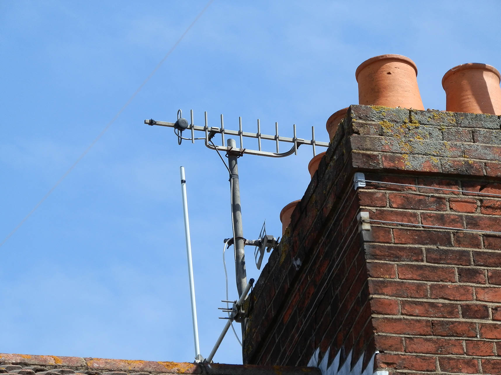
- The old TV aerials
-

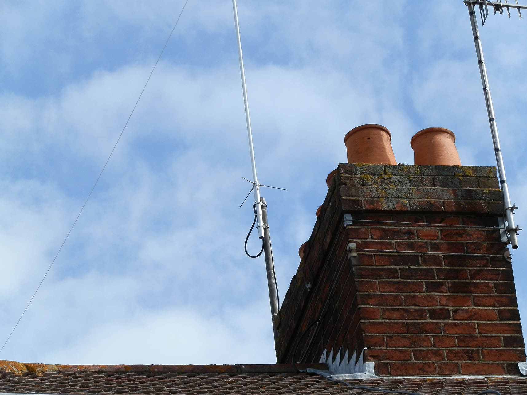
- The Watson W50 collinear
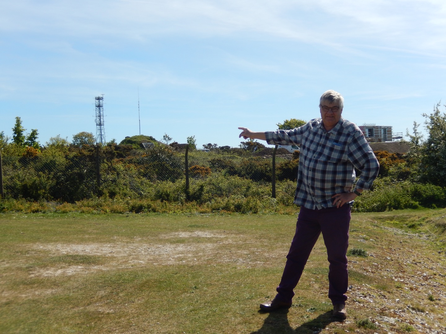
Here I am at the site of GB3IW, the 70cms repeater on the Isle of Wight. The repeater aerial is the one on the right, on the small hill. I don’t know what the huge tower to the left is for but it’s covered in VHF and UHF folded dipoles. The view from the site is amazing. It’s virtually line of sight across the sea to Worthing, where I live. It’s no wonder I can access the repeater with a hand held in Worthing. More Isle of Wight photos here.
Talking of aerials, I’ve just ordered a 70cms 10 element beam and some RG213 coax. I’m not going to get into towers and rotators so I might stick the beam on a pole and turn it by hand. There are several repeaters to the west of my location, Hampshire, Dorset, Devon, Cornwall… so I might leave it pointing in that direction. Great for simplex QSOs, too. It might be interesting during lift conditions.
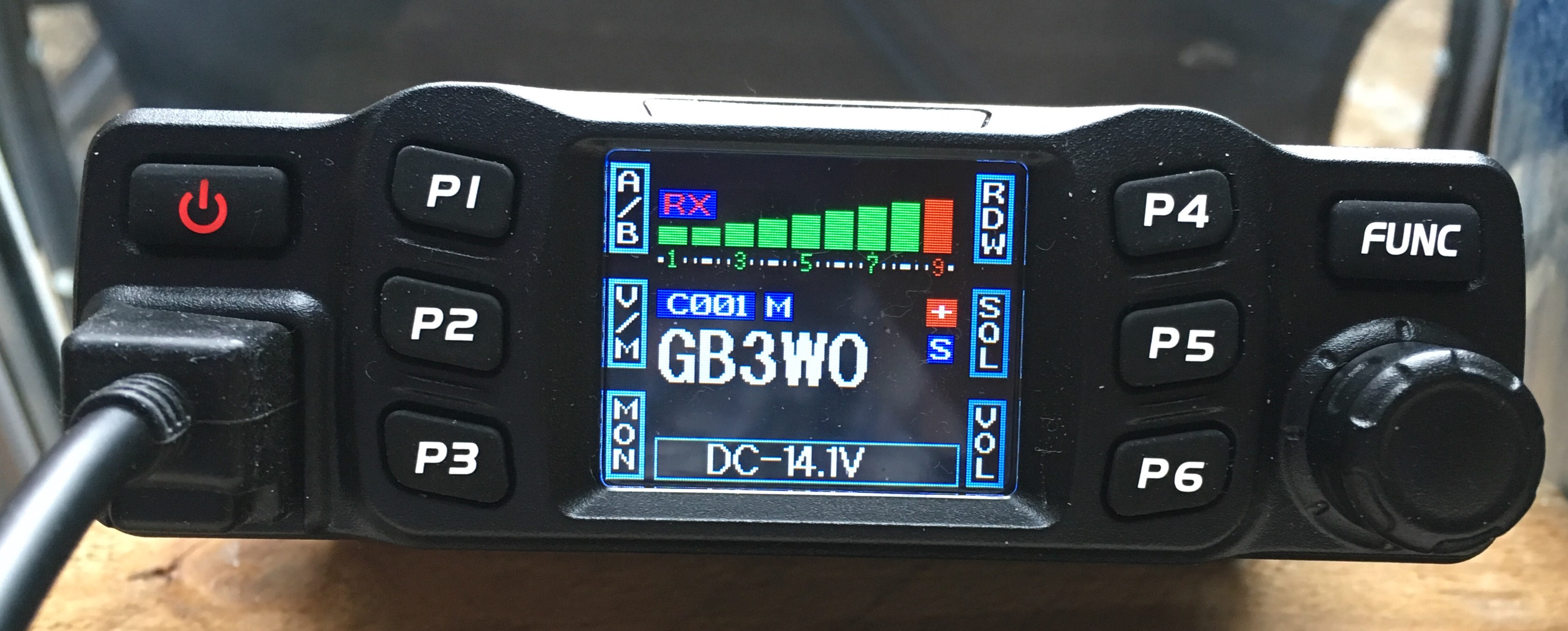 This is the radio I’m using with the Watson W50 aerial. It’s an Anytone model AT-778UV 2 metre and 70cms FM transceiver. I’m really impressed with this radio. Transmitter power is selectable, 5, 15 and 25 Watts, which is perfect for my needs. The radio also covers the VHF marine band… transmit and receive.
HF COMMUNICATIONS RECEIVERS:
This is my Marconi CR100 communications receiver. They were 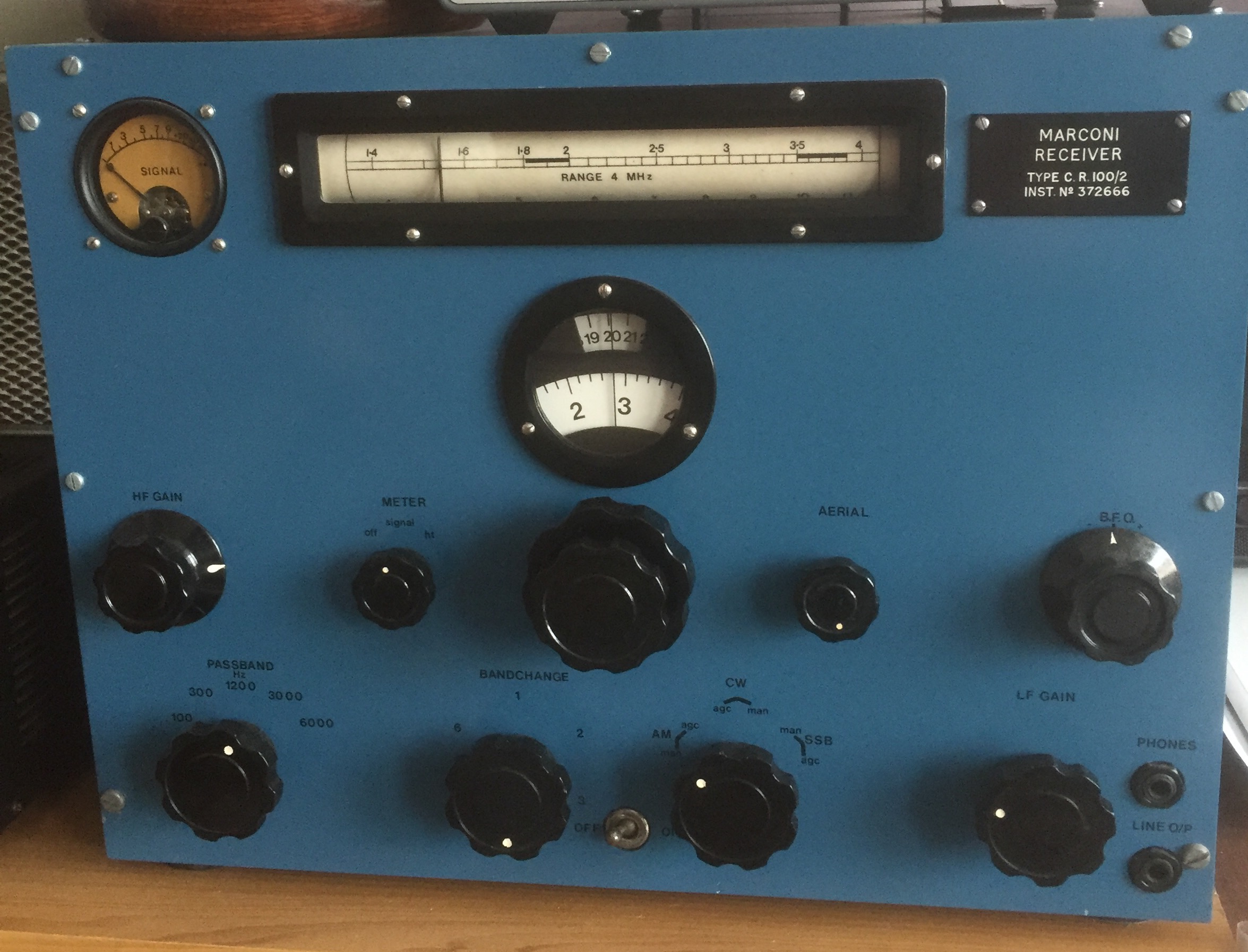 popular in the 1960s but are fairly rare these days. This isn’t my original receiver from the good old days but it’s a lovely example. I spent many happy hours listening to the CCF frequencies, the trawler band, the amateur and broadcast bands and much more. The aerial I use for the CR100 is a simple wire, about 80 feet long and 30 feet high.
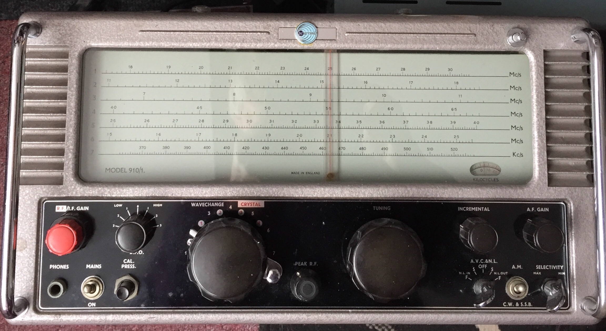
How about this for a communications receiver? It’s my Eddystone 910/1. I’ve had this radio for a good few years and, after a full realignment, it’s working really well. It covers what was the 500kHz marine band but not medium wave, which is a shame. Short wave coverage is 1.5 to 30 mHz.
 Remember the trawler band? It covered approximately 1.7 to 3.3 Mc/s and was full of ships’ comms and coast guard stations, not to mention fishing vessels and other craft. The good news is, the trawler band is not dead. Have a tune around during the evenings and, with patience, you’ll be surprised what you’ll hear. I’ll be listing some interesting frequencies later.
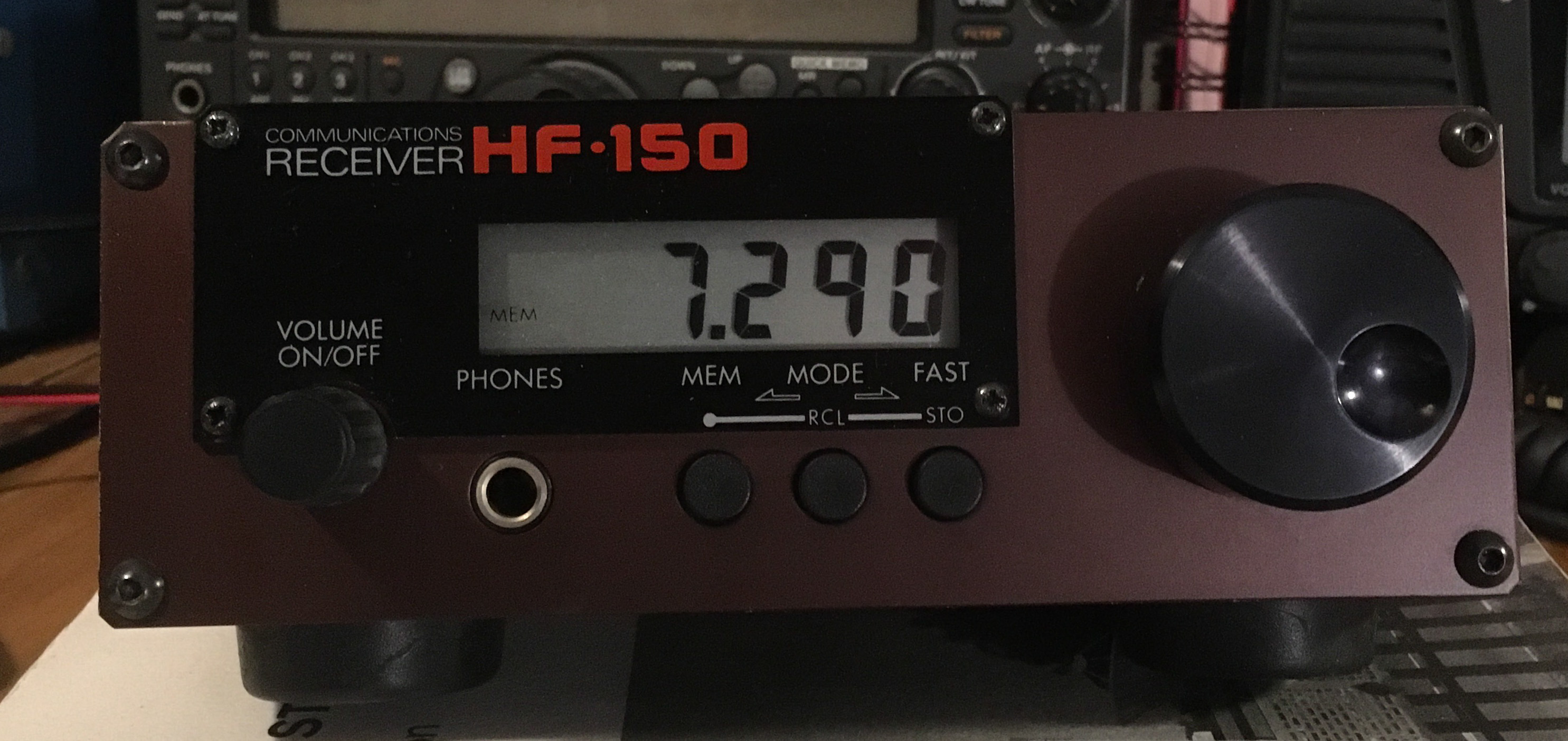 I’m very pleased with this wonderful little communications receiver. It’s a Lowe HF150 covering 30kHz to 30MHz. I’ve been offered a great deal of cash for this radio… but it’s not for sale! There’s more on this vintage gem here.
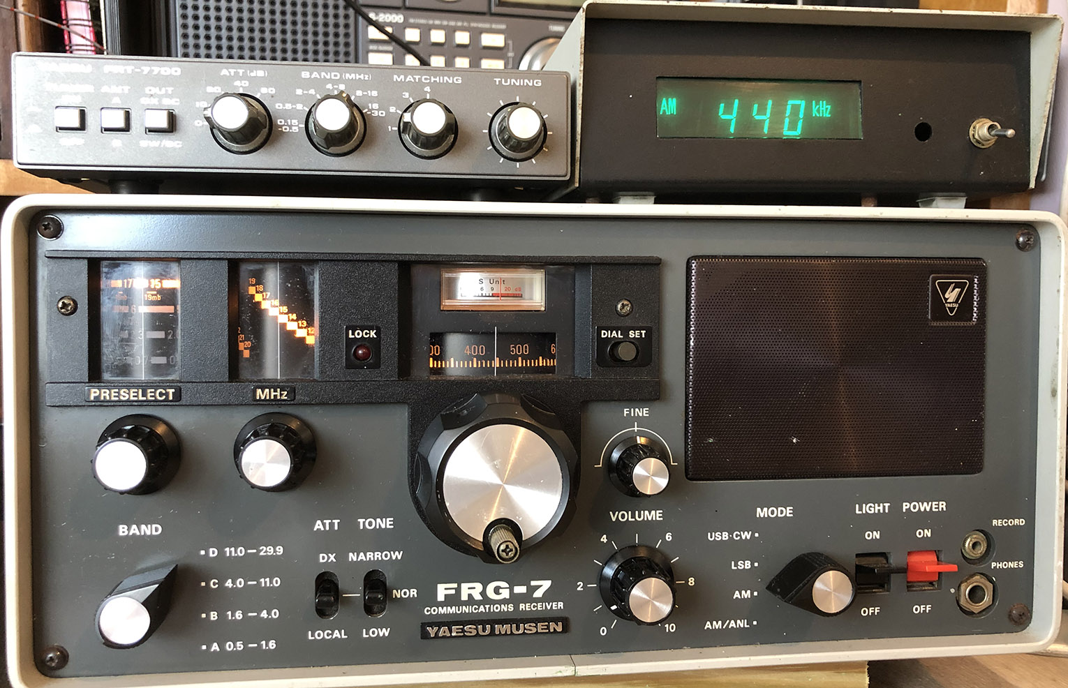
And how about this one… it’s a Yaesu FRG-7 with digital readout box and the matching FRT-7700 ATU. I like this vintage communications receiver. It’s great to use and it works really well. No, it’s not for sale!
Marconi Power Meter:
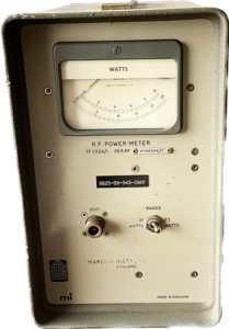 This is a very useful piece of test gear. Rated at 25 Watts, it’s good from 1MHz up to at least 200MHz. I’ve owned this for many years and I’ll never let it go. Obviously, it’s great 50 ohm load as well as a power meter. I’ve used this on just about everything from 19 sets, CB radios, amateur radio gear, medium wave transmitters to handheld radios.
NanoVNA Vector Network Analyser:
Check out my tests and videos on the amazing NanoVNa here.
![]()
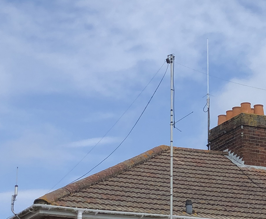
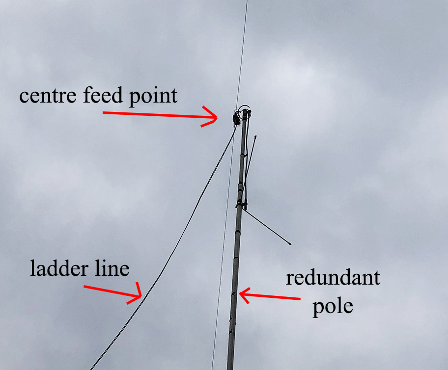
Aerials on the roof:
This left-hand photo shows my PMR 446 antenna, bottom left of the pic. The 70cms – 2 metre colinear on the chimney. And the remains of a Ringo Ranger pole supporting the centre of my 132 foot doublet. The right-hand photo is a detailed shot of the doublet. The centre is about 30 feet high, the ends slope down to about 20 feet.
Radiosonde weather balloons:
This is something new to me. Tracking Radio Sonde weather balloons and, hopefully, finding on on the ground somewhere… it’s a great part of my radio hobby More info here.
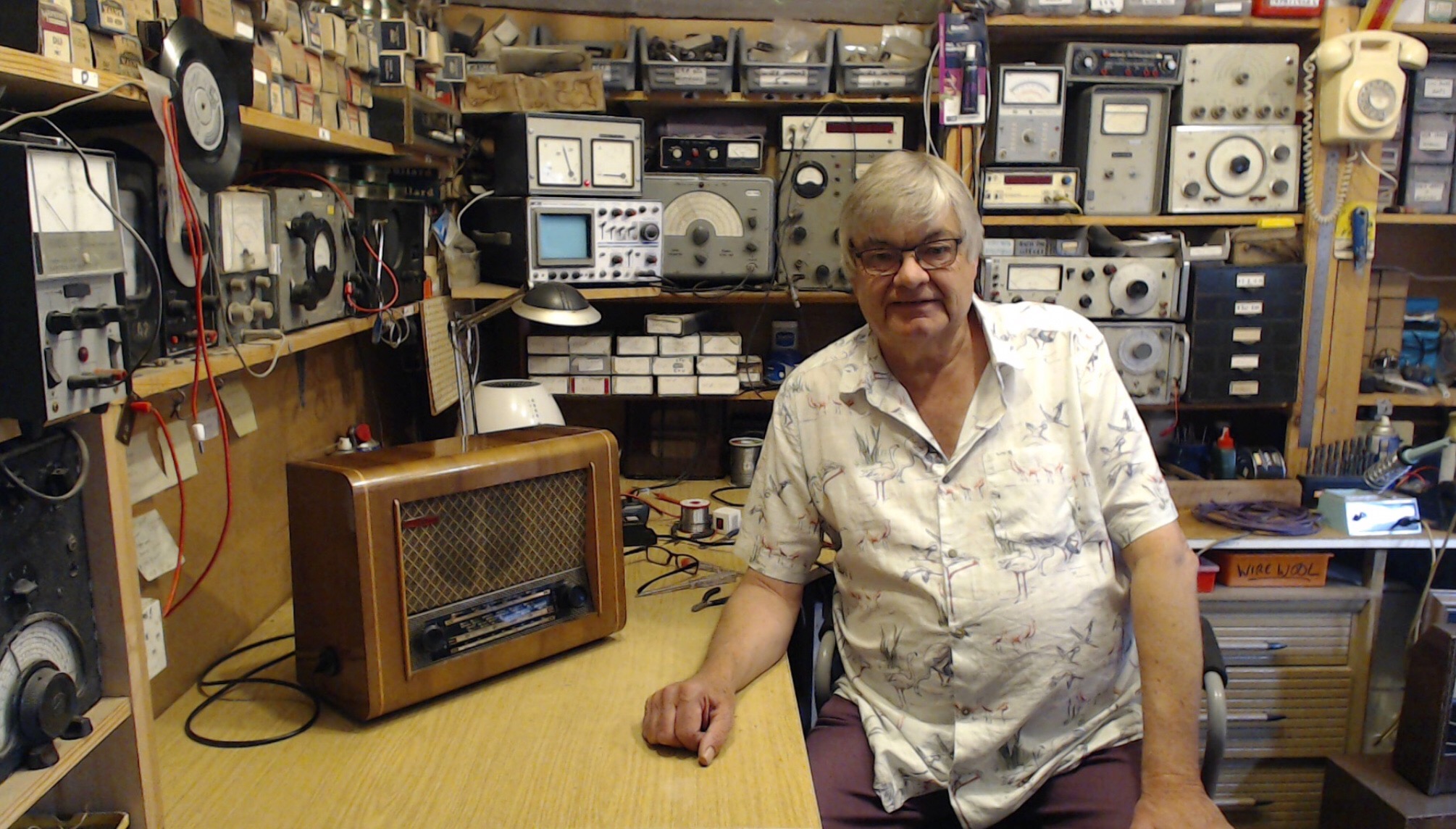
Here I am in The Radio Workshop:
This was taken just before my retirement in the spring of 2021. I now have all the time in the world to play amateur radio.
Give me a shout on GB3RW or GB3BR if you’re within range of the repeaters. I’m usually listening during week days.
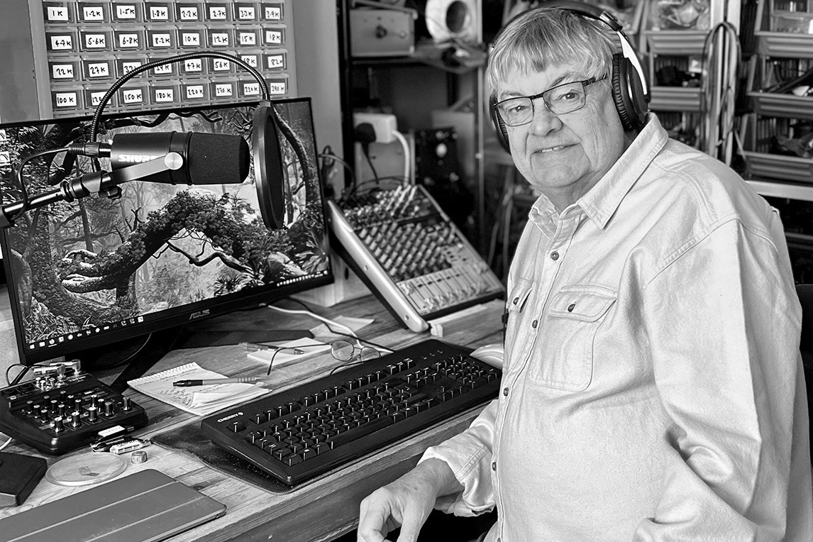
Recording a podcast episode:
Listen to my podcasts here.
Visit the Radio Workshop website here.
Contact email: [email protected]
Please note: I do not repair amateur radio equipment.